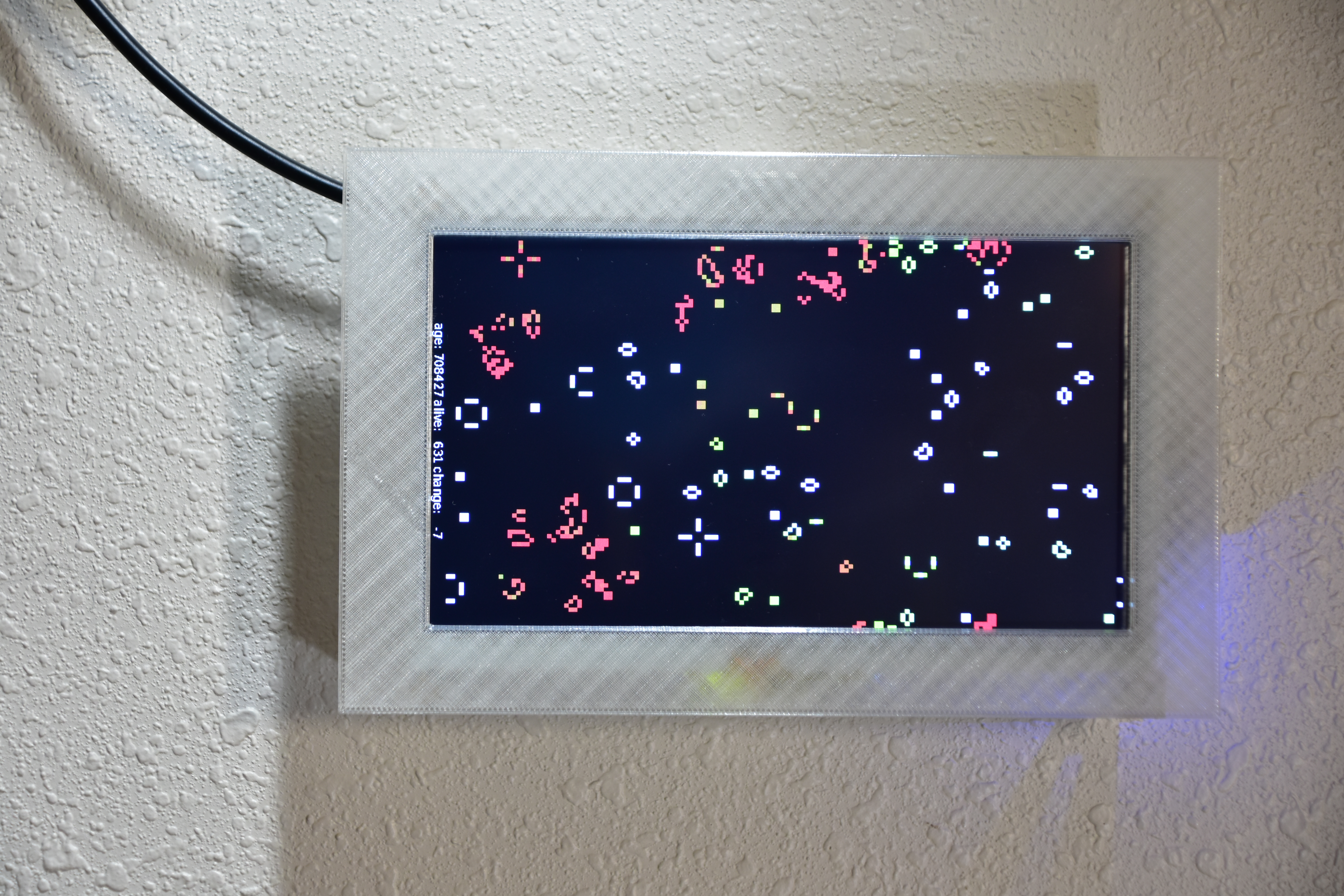
A Touchscreen Life Display
Last year I wrote about my sdl2-life program, adding color to it, and seeding it with data from my website logs. This time I’ve decided to make a dedicated wall display for it using an Adafruit touchscreen display and a Raspberry Pi Zero that I bought back before they became unobtainable.
After a bunch of experiments with the design I managed to make a display that won’t fall off the wall and it looks reasonably nice. The OpenSCAD and STL files can be found here .
The display dimensions are documented here, but the relationship between the viewing area and the mounting holes was a bit harder to figure out. I also wasn’t sure how to attach everything since I wanted to avoid printing with scaffolding or visible screws.
I made quite a few test prints, experimenting with attaching the front of the frame to the display with clips. I wanted it to fit flush, but the posts were pretty short and easy to break off when assembling it. I saved time by only printing one edge and combining it with the cutout for the display area. This is easy to do in OpenSCAD – you just wrap everything in a difference() block and ’erase’ most of the design with a big cube.
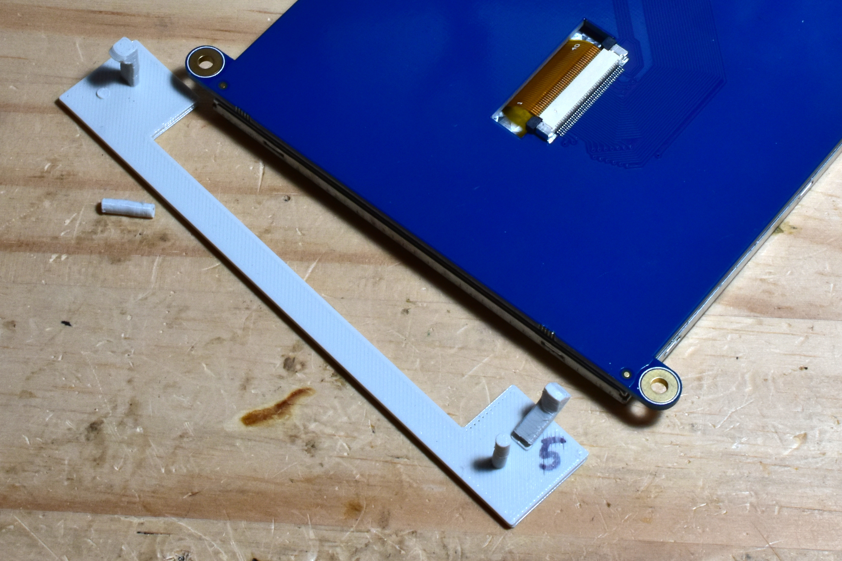
Then I tried a circular standoff with thin sides to capture the display’s mounting tabs, but that was just as hard to put together due to the short length of the clips.
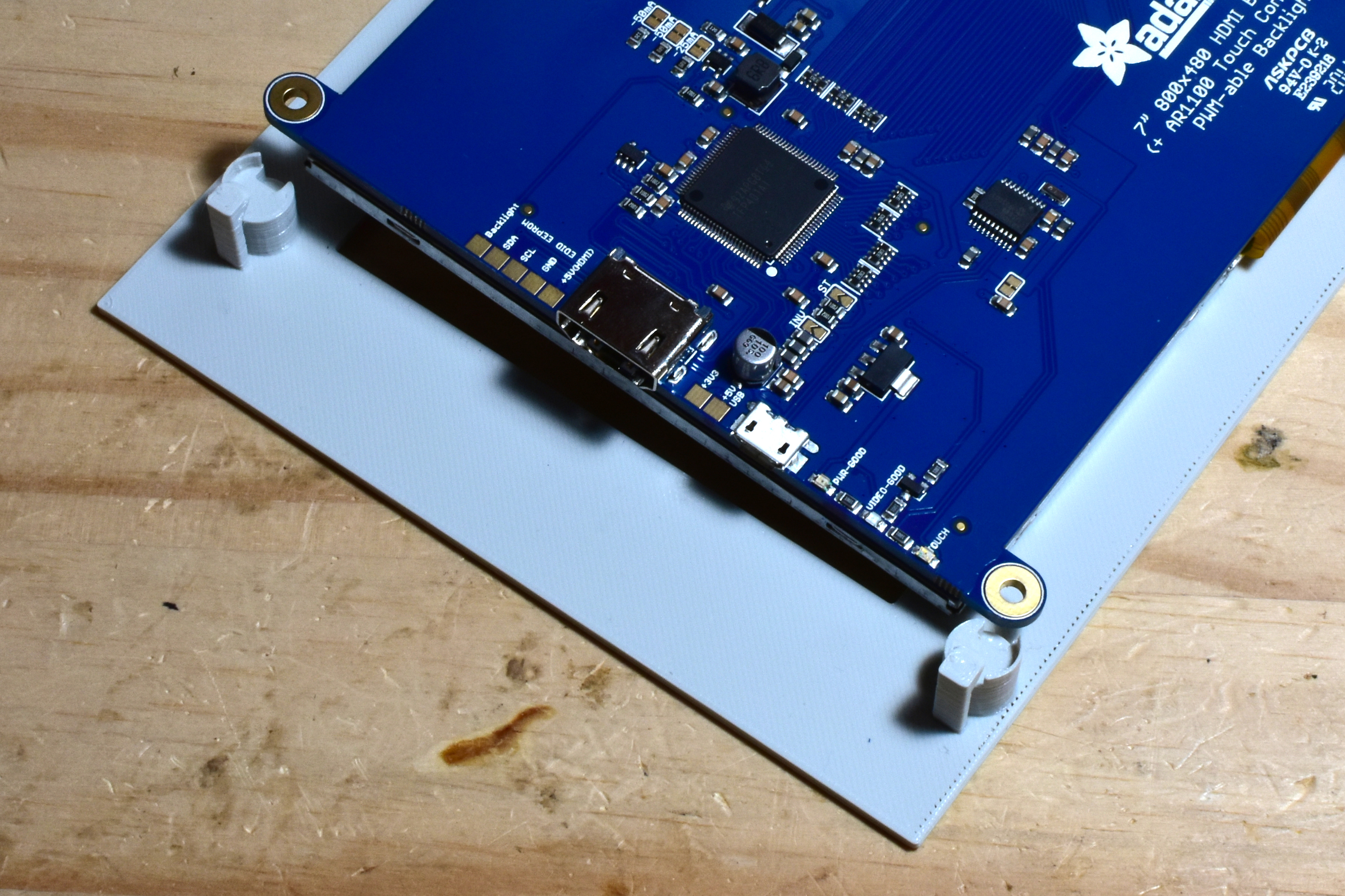
The solution is to mount the display to the back first, using longer pins and latches which allows them to be more flexible without breaking.
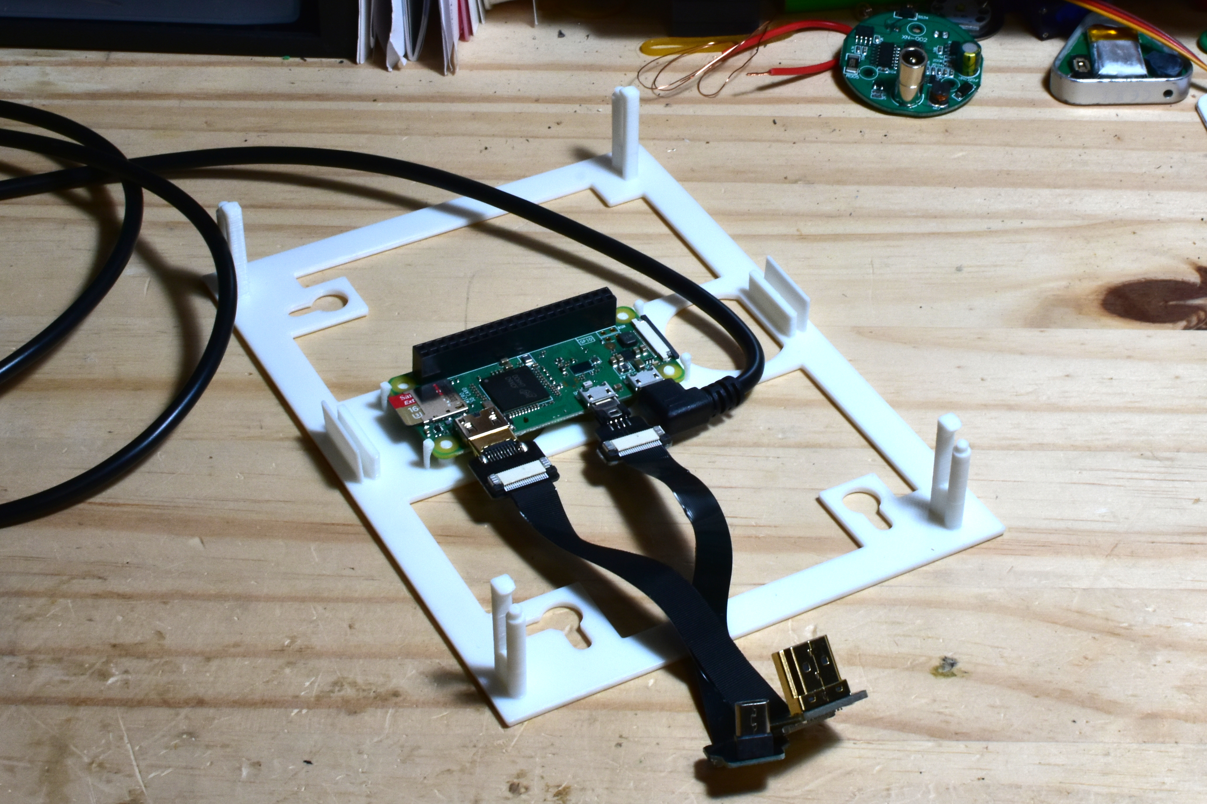
The back of the frame mounts to the wall with screw slots and can be oriented
in landscape or portrait, you just have to pass the -rotate angle to
sdl2-life. The Raspberry Pi zero is in the center, allowing enough room for
the extra cable length without kinking them. I used the Adafruit ribbon
cables
for the HDMI and USB connections
between the display and the Pi.
The slots on the side have a cylinder shape in the center so that the mounts on the front can just snap into place. The outside wall helps put pressure on the latch to keep it in place.
The front now mounts to the back instead of to the display, using a couple of long walls with cylindrical nubs that hold it in place. 4 corners orient it around the display’s mounting tabs.
It is still a bit loose, and would benefit from using 4 attachment points closer to the corners instead of the 2 on the sides, but for now it stays attached well enough.
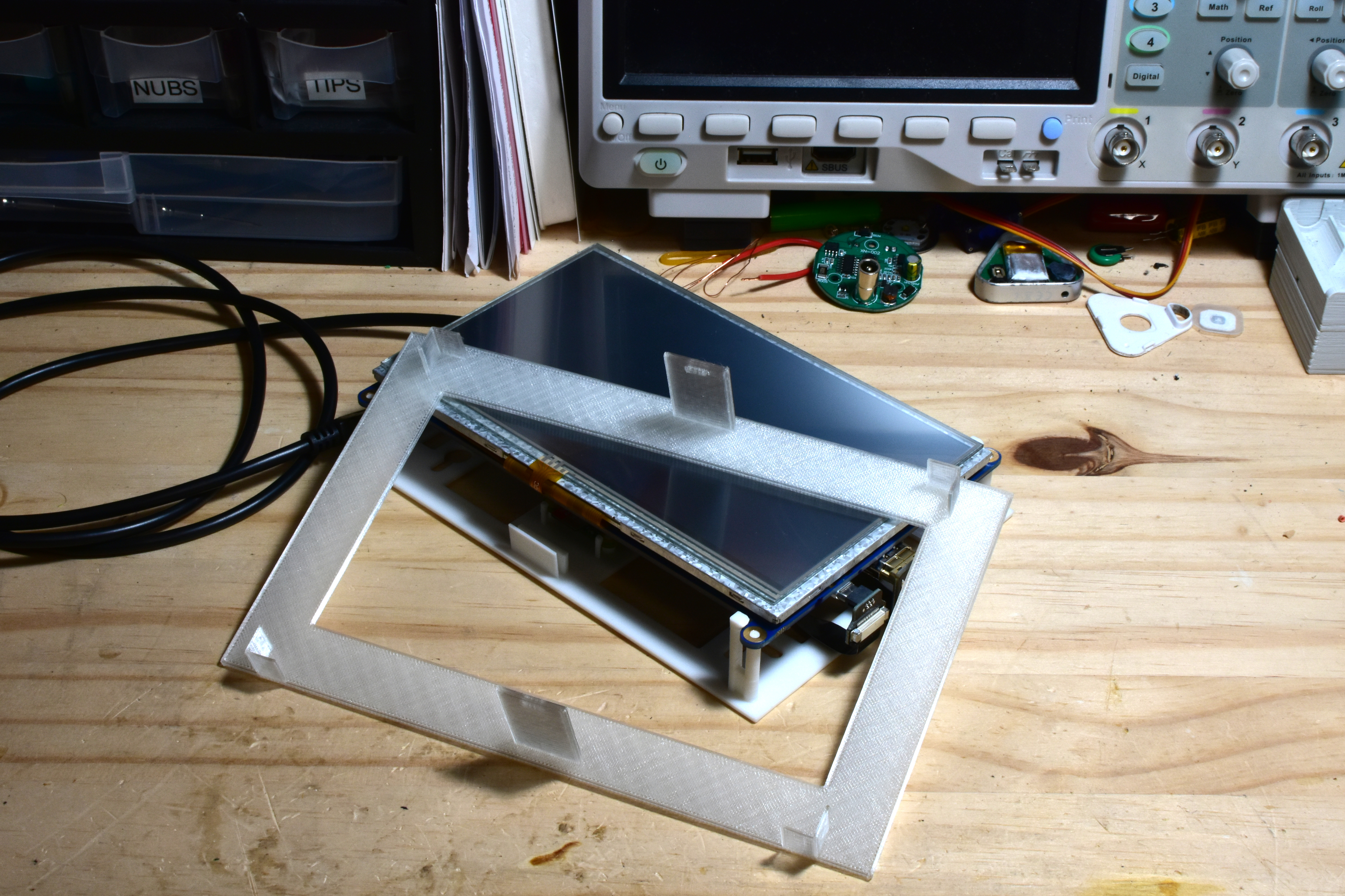
The assembled and running display looks like this:
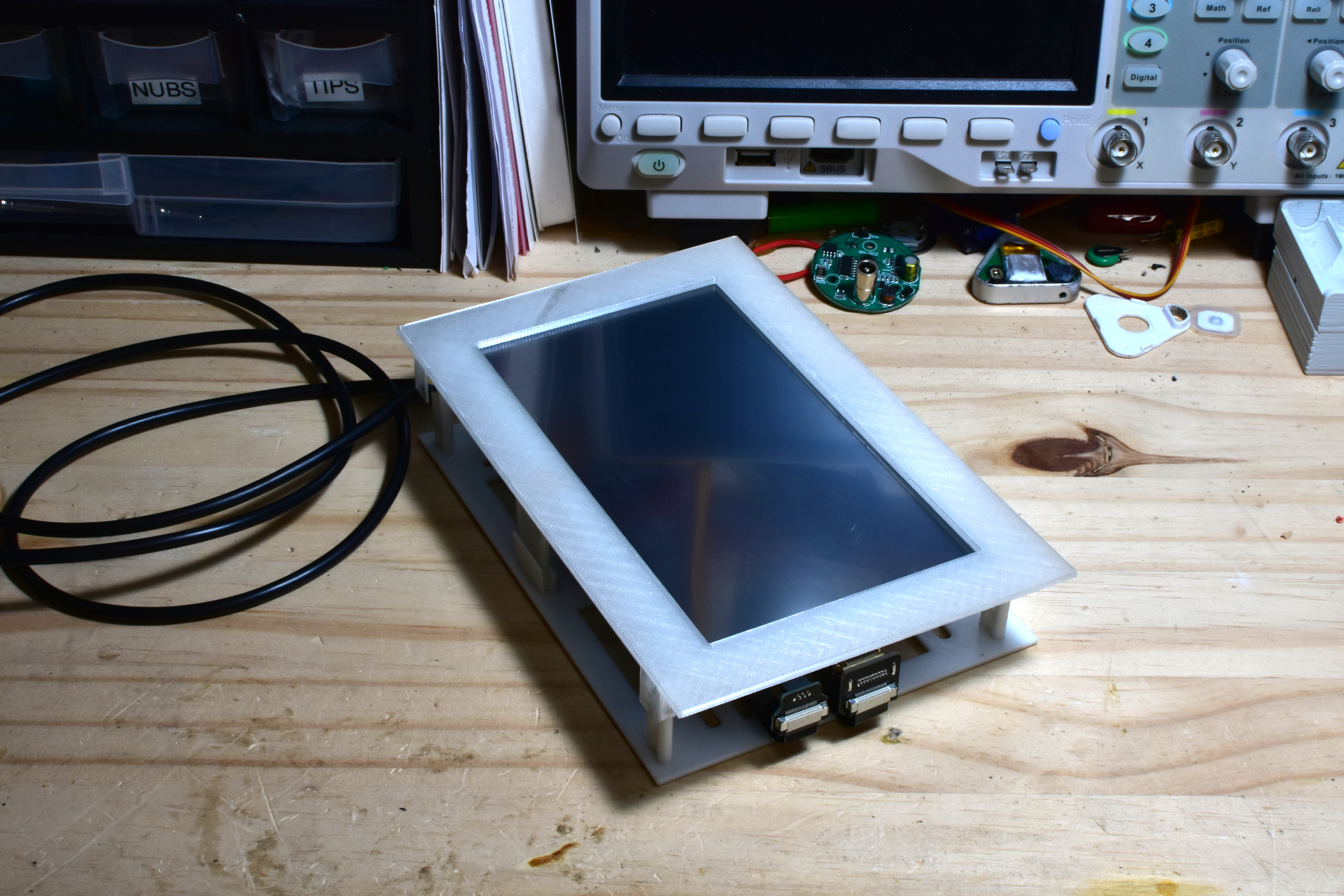
The final print of the front was with Amazon Basics transparent PLA filament, you can see the Pi and display status leds visible through it. But due to the print pattern it really isn’t as transparent as advertised.